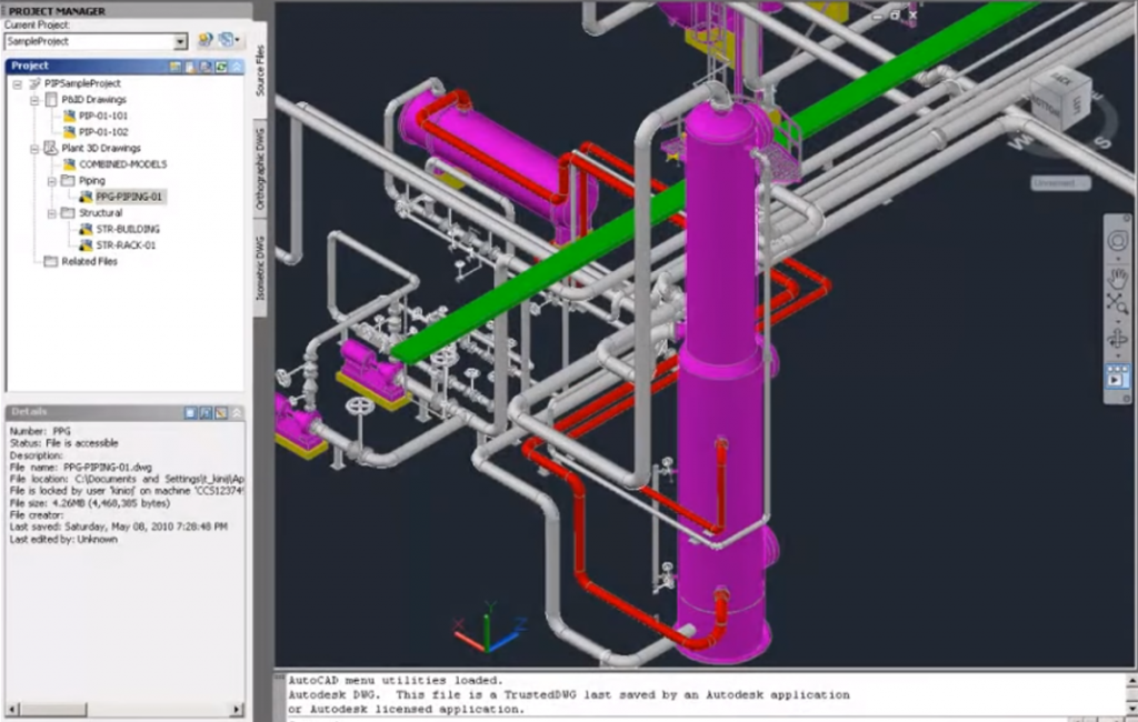
AutoCAD Plant 3D is a powerful toolset for plant design. It offers a wide range of features that are specifically designed for the needs of plant designers and engineers. These features include:
- A comprehensive library of industry-standard symbols
- Powerful 3D modeling tools
- Advanced design automation features
- Integrated reporting and documentation tools

In this blog we’ll explore the differences in using the AutoCAD Plant 3D Toolset over:
- AutoCAD LT and AutoCAD
- MCAD software such as Autodesk Inventor and Dassault Systemes Solidworks
- BIM software such as Revit
Advantages of AutoCAD Plant 3D over AutoCAD LT
AutoCAD LT is a less expensive version of AutoCAD that is designed for 2D drafting and design. It does not offer the same level of features as AutoCAD Plant 3D, including:
- Industry-standard symbols
- 3D modeling tools
- Design automation features
- Integrated reporting and documentation tools
Advantages of AutoCAD Plant 3D over AutoCAD
AutoCAD is a more powerful version of AutoCAD LT that offers a wider range of features. However, it does not offer the same level of specialization for plant design as AutoCAD Plant 3D. AutoCAD Plant 3D includes features that are specifically designed for plant design, such as:
- A comprehensive library of industry-standard symbols
- Advanced 3D modeling tools
- Design automation features
- Integrated reporting and documentation tools
Advantages of AutoCAD Plant 3D over Mechanical CAD Software
Mechanical CAD software is designed for the design of mechanical parts and assemblies. It does not offer the same level of features as AutoCAD Plant 3D for plant design, such as:
- Industry-standard symbols
- Piping and instrumentation diagrams (P&IDs)
- Electrical diagrams
- Structural drawings
- Integrated reporting and documentation tools

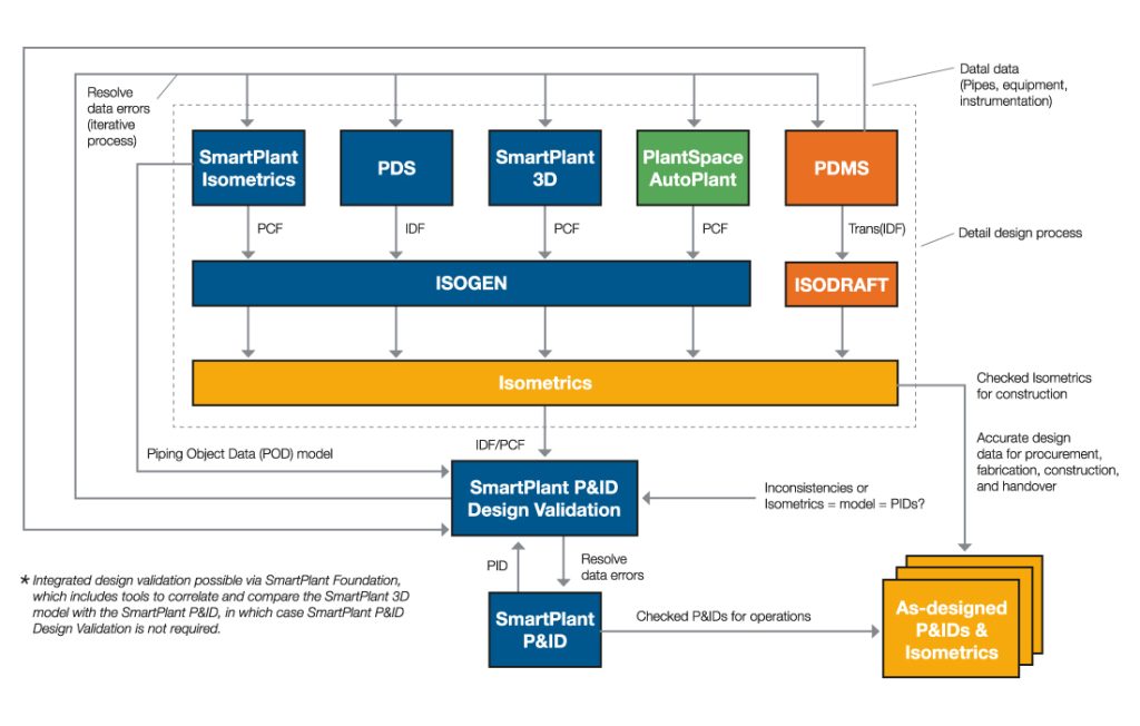
What Is a Smart P&ID?
A smart P&ID, also called intelligent P&ID, takes a P&ID one step further in terms of usability. It provides additional helpful information that can be used for tracking, understanding, and managing instruments within your piping system.
Before getting too far, let’s take a step back. What is a standard P&ID? It’s a 2D drawing that shows a process flow with respect to the piping and instrumentation used. If you have piping that goes between machines with different temperature sensors, pressure gauges, and line sizes, this information would be captured and drawn within the P&ID.
A standard P&ID can be used by a number of different engineers to understand what’s going on in your facility. They’re really useful when you need to upgrade or retrofit any section of piping.
A smart P&ID takes all the information associated with a standard P&ID and goes further. For starters, a lot of the symbols and lines have associated text that needs to be filled out when an engineer adds them to the drawing.
For instance, after adding a pressure gauge symbol, a smart P&ID will prompt the engineer to include the pressure range of the gauge, the ID label, and size of the NPT thread on the base.
In addition, the symbol is automatically inserted at the right size and has a leader that can be dragged into position.
In more advanced intelligent P&ID systems, this data can link into a central INFOplant database. If your facilities are already linked to this software, you can access this data from a number of different places, quickly sharing accurate data about your process.
Example of Using a Smart P&ID
If we were to make a new P&ID today, we would default to an intelligent P&ID template. We have libraries of different symbols that can be dropped into a P&ID with just a few clicks.
The border is automatically generated, and there are text boxes that pop up whenever we insert a symbol. These pop-ups ask the engineer to add important information that automatically gets attached to the symbol that’s placed.
We could make a hundred P&IDs for your project, and all of the symbols, borders, and line sizes will be the same across the board. There is no more guesswork associated with putting together a P&ID, as long as you know the process specs for the lines and instruments.
Who Should Use Smart P&IDs?
A smart P&ID is useful for any company that has to maintain, track, and install piping within their facility. This includes most manufacturing plants, especially ones that handle chemicals or use industrial equipment.
Whether you’re making one P&ID or one hundred P&IDs, you can see benefits from swapping to intelligent P&IDs.

The Benefits of a Smart P&ID
Why should you start producing intelligent P&IDs? There are a lot of reasons. Let’s discuss some of the benefits of smart P&IDs so you can answer this question for yourself.
Much Faster to Produce
If you ever made a standard P&ID, you know how long it takes to set up the title block and border, get the right text size, and draw the symbols that you need to use. If you had to repeat this process multiple times, you could be losing entire days’ worth of time just setting up the files.
In addition, there is added time if you forgot to add line sizes or instrumentation details.
With intelligent P&IDs, you’ll get the immediate time save of having your border, symbols, and text automatically generated and ready to input. In addition, all of the information will be added for each line and instrument you include.
Not only does this mean fewer revisions wasting your time, but it also means less time spent drawing every single P&ID. This means that your engineers have more time to work on other projects, since the P&IDs will be generated faster.
Difference between Plant 3D and Smart P&ID
| AutoCAD PLANT 3D | SMART P&ID | |
| Company | Autodesk Founded: 1982 United States | Hexagon PPM Founded: 2017 United States |
| Supported OS | iPhone, iPad, Android, Windows, SaaS/Web | SaaS / Web |
| Support | Phone Support Online | Phone Support 24/7 Live Support Online |
| Pricing | Free Trial | No Free Trial |
| Training | Documentation and Live Online | Documentation and Webinars |
| Integration | Intratech 3D PDF Exporter | PDS |

